Feel free to share your hardware modifications here!
ZIM Hardware-Mods
I had some time last night. And normally I have strange ideas when having free time 
It is a pain to see my beautiful ZIM with loose wires coming out of the back, and knowing that I have to open the case remove the network cable (W-Lan is too weak in my basement).
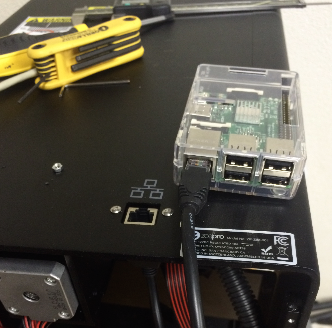
So I ordered some pigtail connectors some time ago and last night was the night to install them:
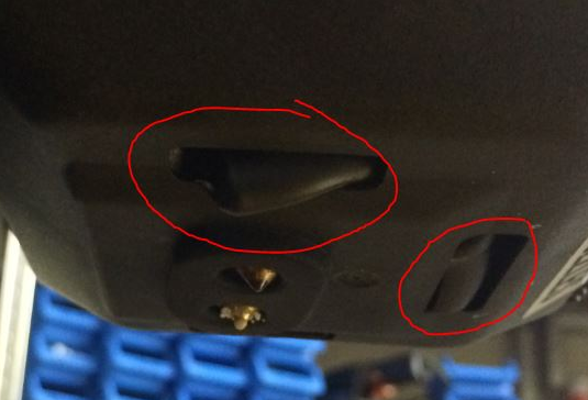
Mark the new cut-outs:
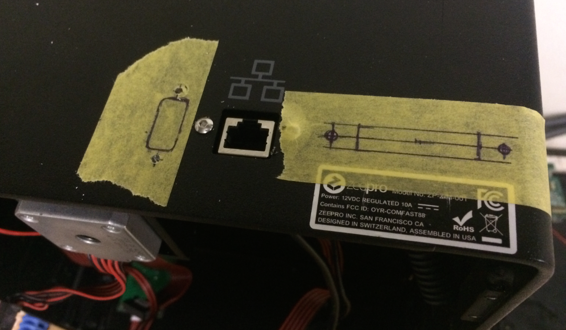
Installed the pigtails:
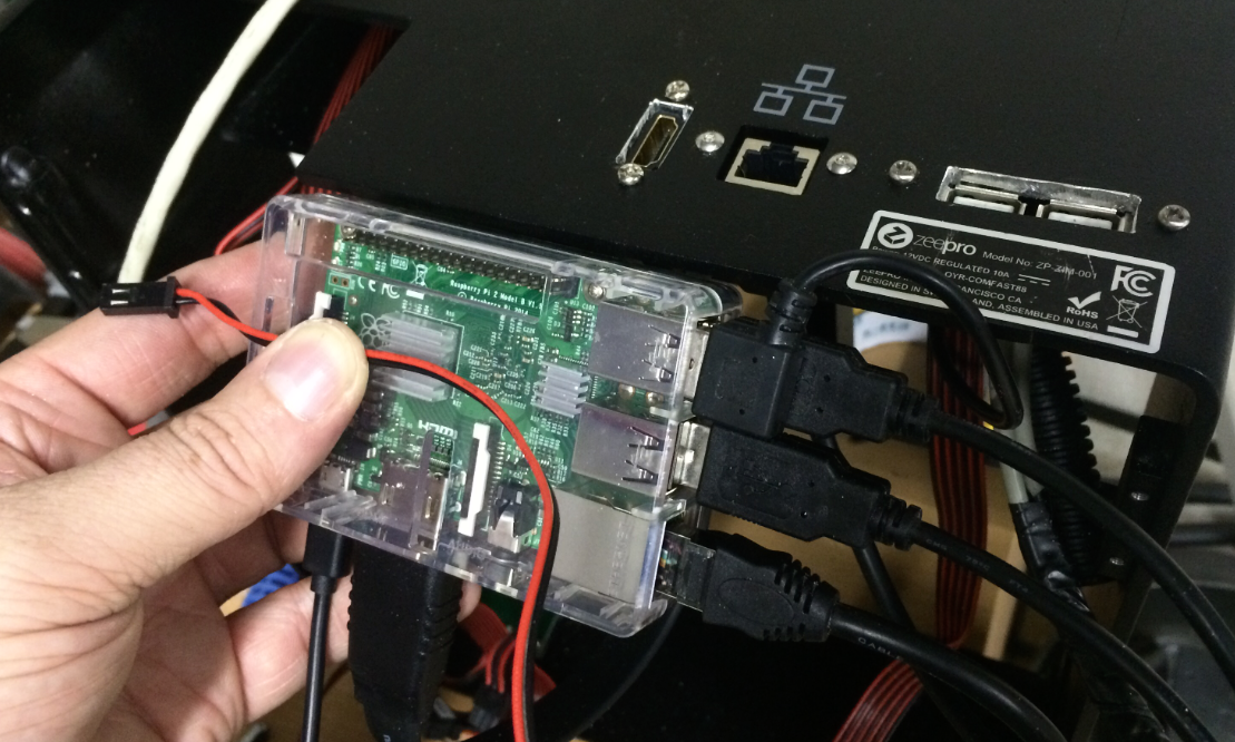
Happy:

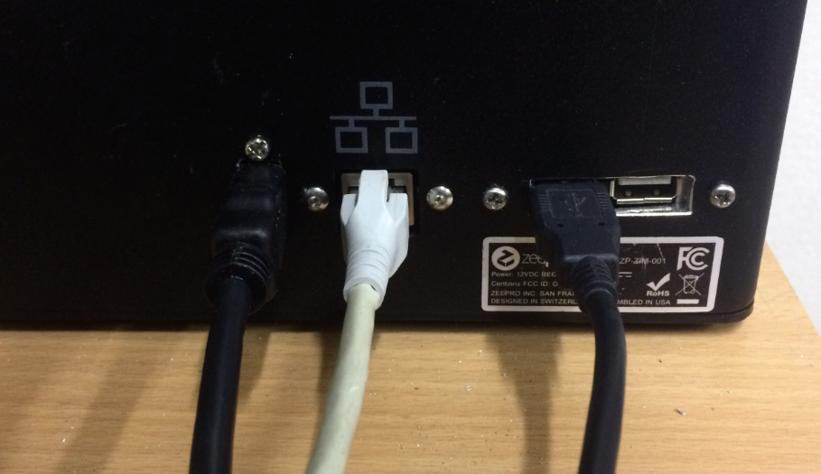
Some matte black color for the cut edges, and that´s all.
And in near future, it´ll get a keyboard, mouse and a display
Future projects:
- move the powersupplies into the Base of ZIM
- Bring the heated bed cables through the body
Ladies and Gentlenerds, 
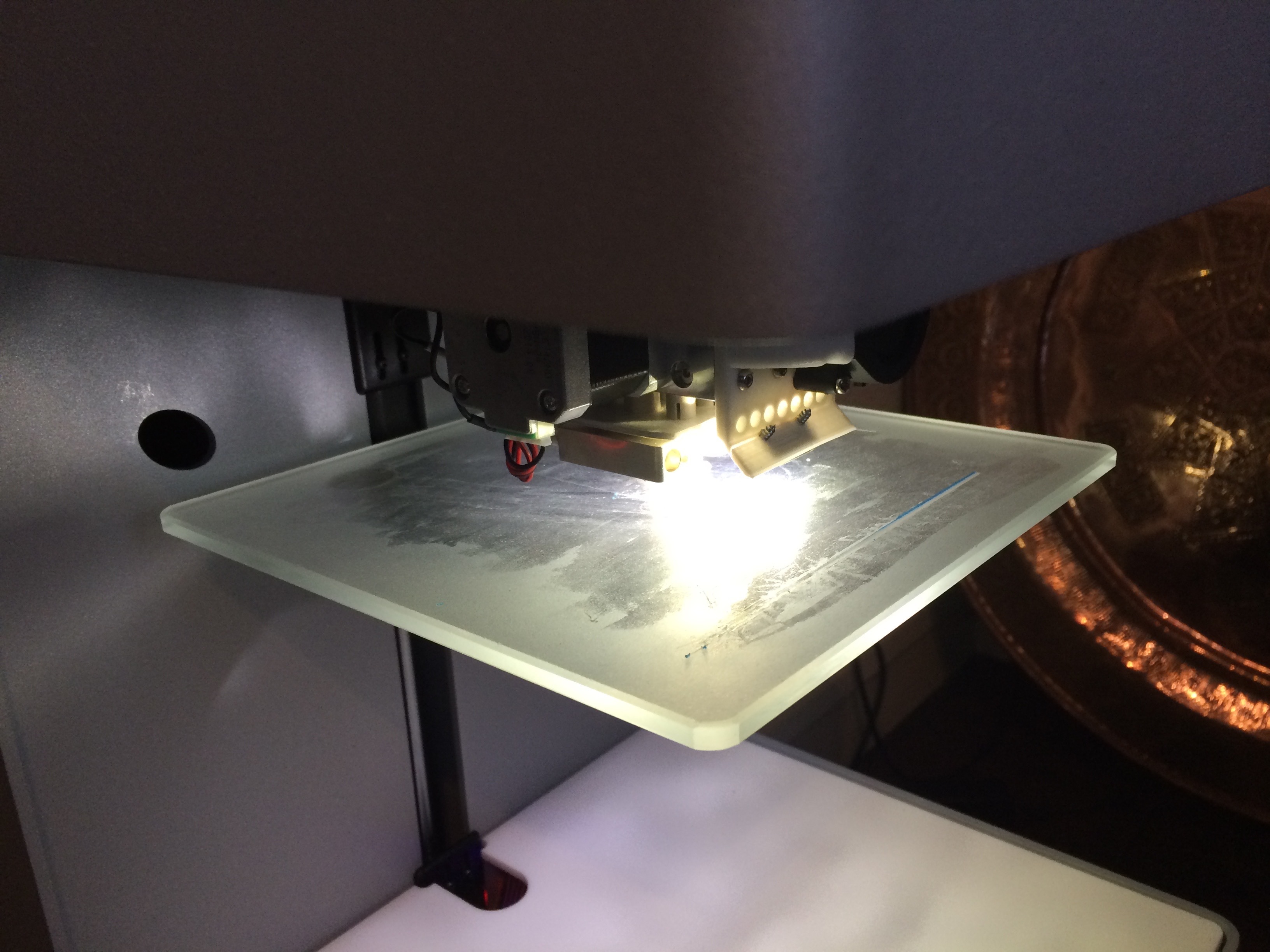
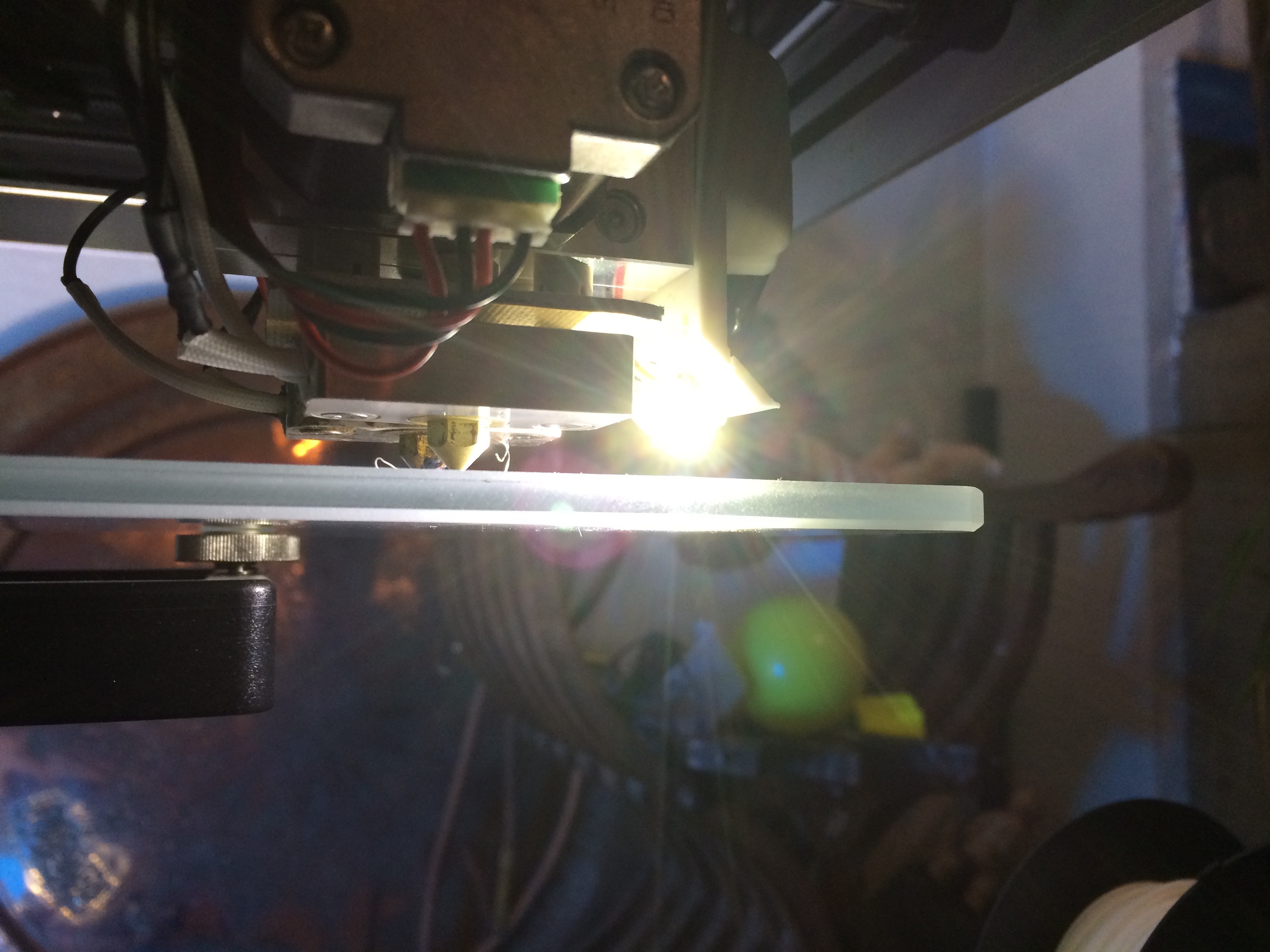
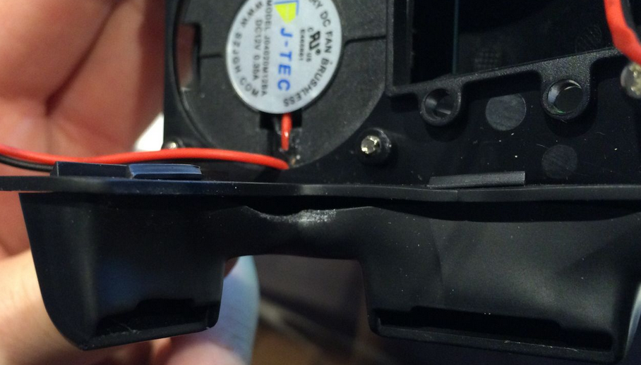
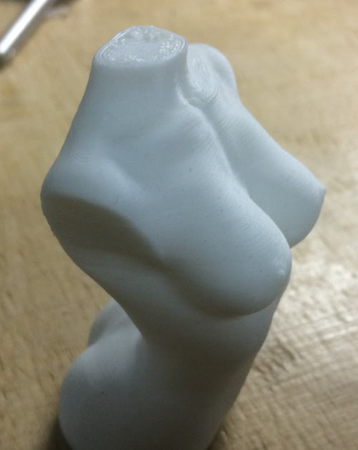
my ZIM´s cooling funnel is completely messed up by the heat radiation of the Hotends and the heated bed:
I contacted Zeepro… But my ticked is
I had a complete part on stock from an earlier claim, but I didn´t integrate it. I think I might have destroyed it the same way. So all the time, I printed without the left cooling fan (also works pretty good: ).
But today, I tried to make a heat deflector for the hotends, so that I can re-integrate the cooler.
So, I took a piece of strong aluminium foil (135 to 18mm) and made a housing for the hotends:
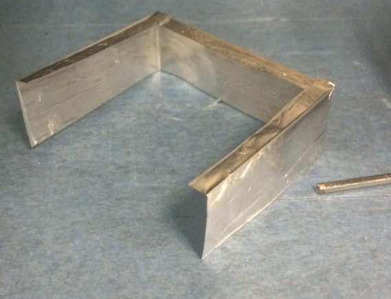 , which simply hangs down from the upper insulation plate:
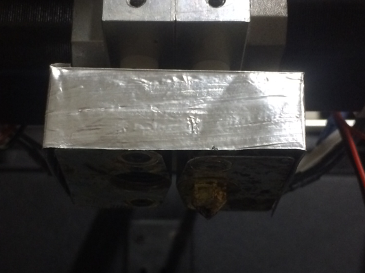
I hope it will help to keep the plastic parts around the hotends a bit cooler. Most important thing is not to touch the hotends with the foil. After mounting the new funnel the deflector looks a bit deformed, but I´m confident…
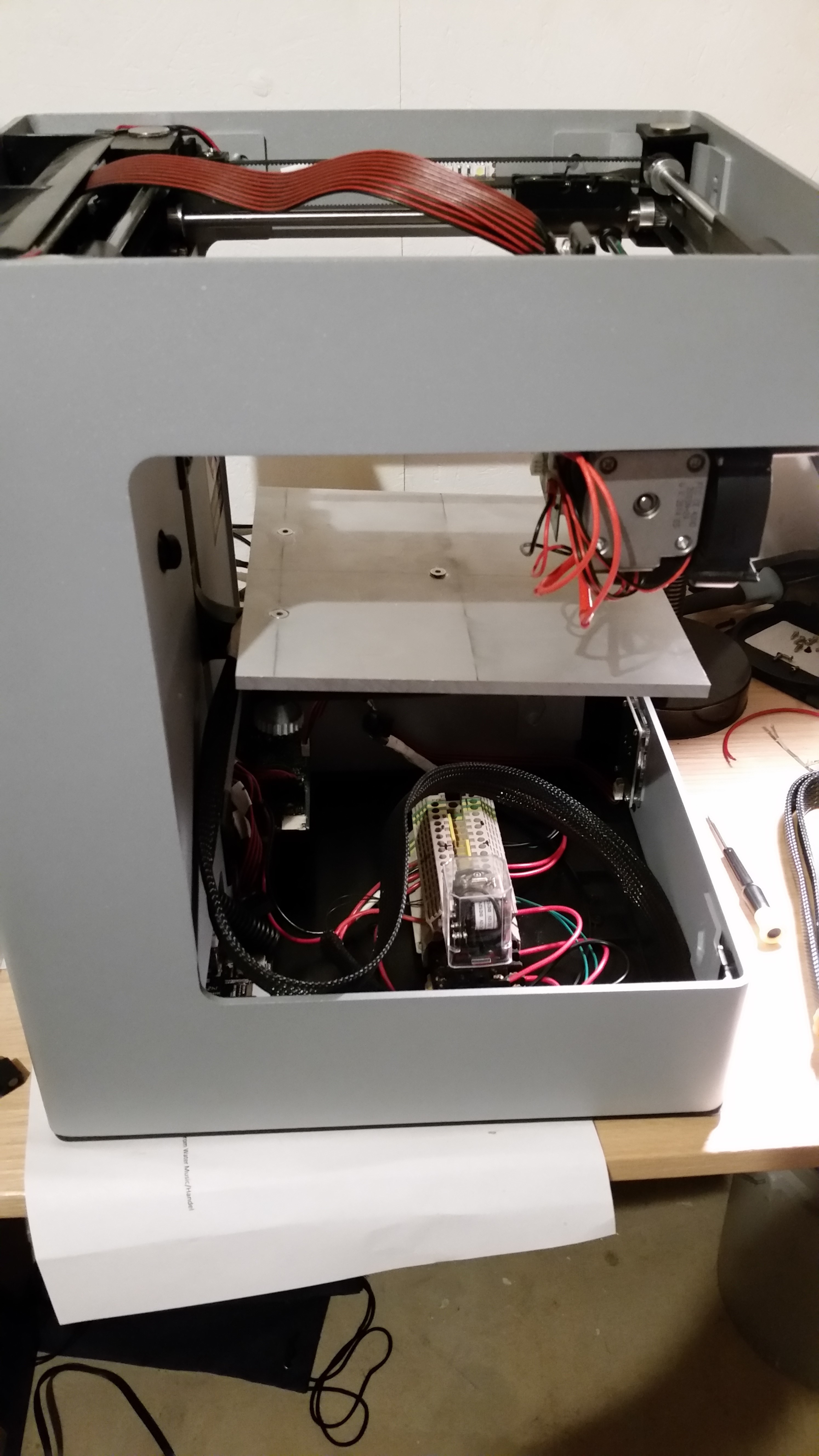
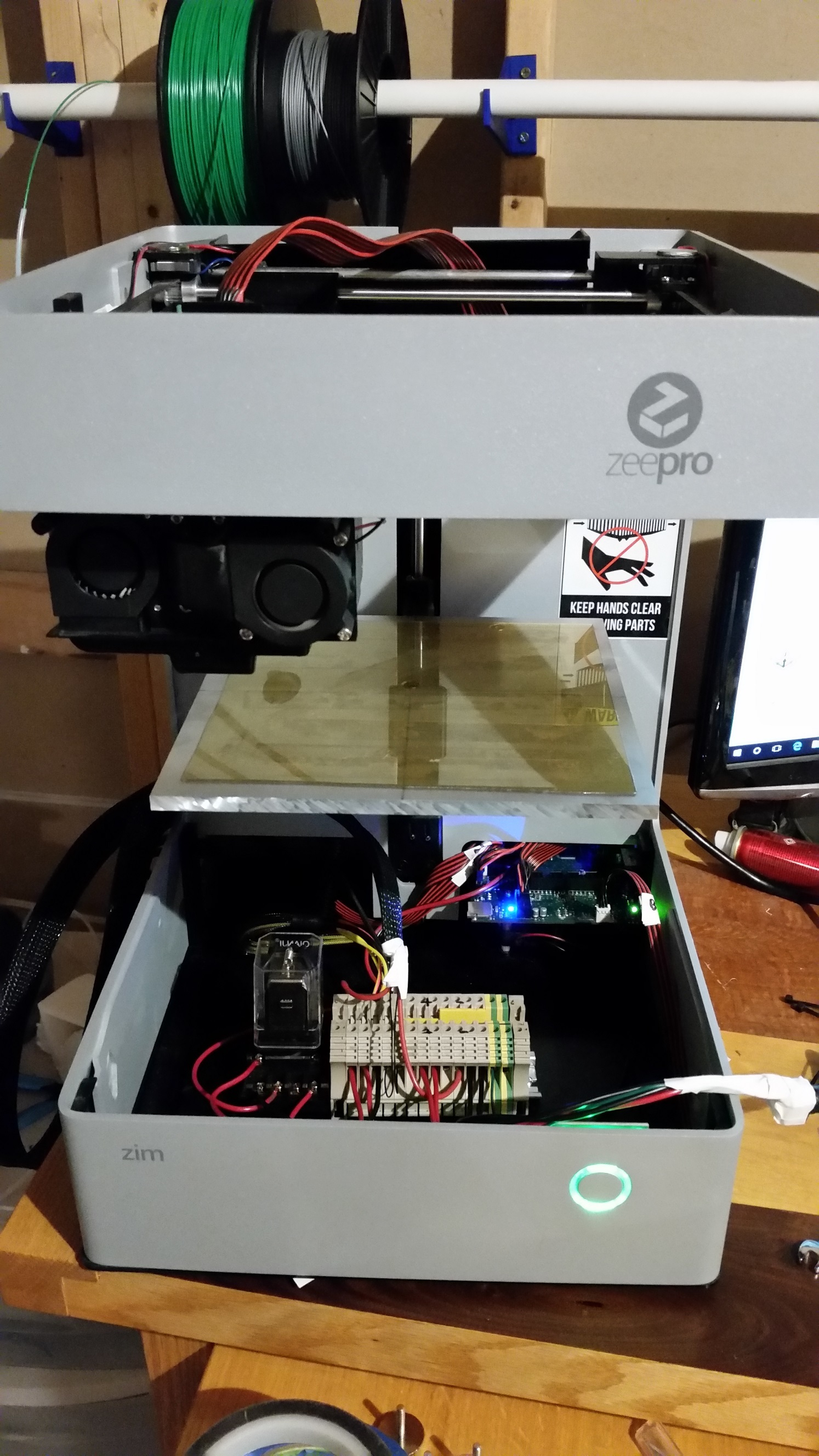
I wired in the new heated bed made out of aluminum after breaking the heated bed that came with the Zim. I used the relay idea so that I’m not running to much current through the control board. This set up hasn’t been tested yet but I will post more pictures and test results after I give it a try.
1 Like
Cool Idea!
I´m really excited how good this setup works!
So it works Now for some more information, the relay I used was the JQX-10F DC 12V Coil General Purpose Relay found on amazon for $8. It has a lot more pins than I needed but its rated for the 10A that I needed and it works so far.
Here are a couple more pictures. If anybody wants me to sketch up the schematic for how I wired it let me know and I will post it. I used the connection I unsoldered off the control board to bring power to the terminal strip so I didn’t have to cut up my power supply.
Looks great! I’d like to see how you wired that. Does it take any longer to bring that hunk of aluminum up to temperature than the stock setup?
I haven’t done any ABS tests with either bed so I don’t know about high temperatures but bringing it up to 60 deg for PLA seems to be about the same as the original bed. If your going to copy the design I used 1/4" aluminum since that was what I found cheap on amazon but I would recommend something thinner since its a bit heavy on the front spring and compresses it more than I would like to get it level.
I will try and take a few minutes today or tomorrow and draw up the wiring schematic and get it uploaded.
Here is a screen shot of the wiring schematic. I drew it in autocad but it won’t let me upload the .dwg file.
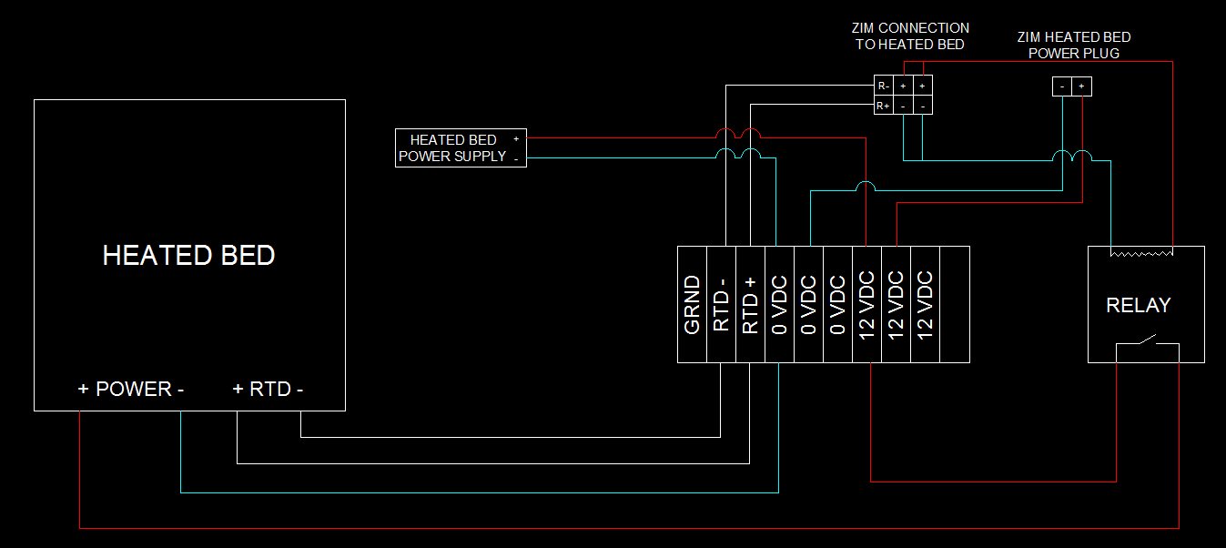
Perfect, thanks for posting this info. Do you know what the “zim heated bed power plug” is for? It doesn’t look like it is used. Is that so you can switch over from a relay back to using the zim board?
I don’t know for sure but I’m pretty sure the Zim Heated Bed Power Plug provides the power to the zim to activate the relay.
What are full hardware specifications for your machine? What type of MCU it contains and what are other control units?
Also which power supply is required for it?
Is it possible to modify it according to the requirement?
Mine is running on the Zim control board with a new USB port and a connection to my PC. I’m using the heated bed power supply that came with the Zim heated bed which is 12Vdc and 10 amps to run the heated bed and then the original zim power supply to power the control board and stepper motors.
A shield to prevent the airflow from the left fan to cool down the heated nozzle, was one of my many important things to do.
J_Schmidt did a great job and had a fantastic idea first.
I improved it a bit further, because I still had nozzle cooldown problems when running the fan on 100%. So I incorporated the bottom heatshield plate that was in the head cover.
Here is my idea:

The protoype looks like this:
Now “simply” bend some metal sheet and its ready.
I am going to post a follow up with the final build.
2 Likes
Okay, tried the first print with the “heatshield” today… Worked pretty well. 100% Fan and absolutely no temperature problems at the nozzle. (With headcover attached, of course)
I´ll have an eye on this… and report my long-term-experiences
My design is a failure. Sorry for that.
It does improve but not enough and furthermore the sides are in the way of where the air should be blowing.
60% cooling fan is all thats possible.
There needs to be a different design where the air is directly blown to the nozzle and some heat shield solution.
I am not capable of doing that.
A failure? Not really.
At LEAST you gained experience.
But really, I can´t believe that your design doesn´t work… Mine works perfectly, and I only use strong aluminium foil. AND: My shield isn´t closed like yours! Maybe you should give it another try… Does your shield touch the heaters? It must not!
Or maybe it is because I closed all small gaps in the funnel with Epoxy? It´s also important that the air outlets go completely through the Cover of the head, so that no air is blown to the inside of the head cover. And you have to use the silicone nozzle-protection-shield-thing to avoid the air cooling down your brass nozzles.
Ok, not a complete failure but not successful enough for me.
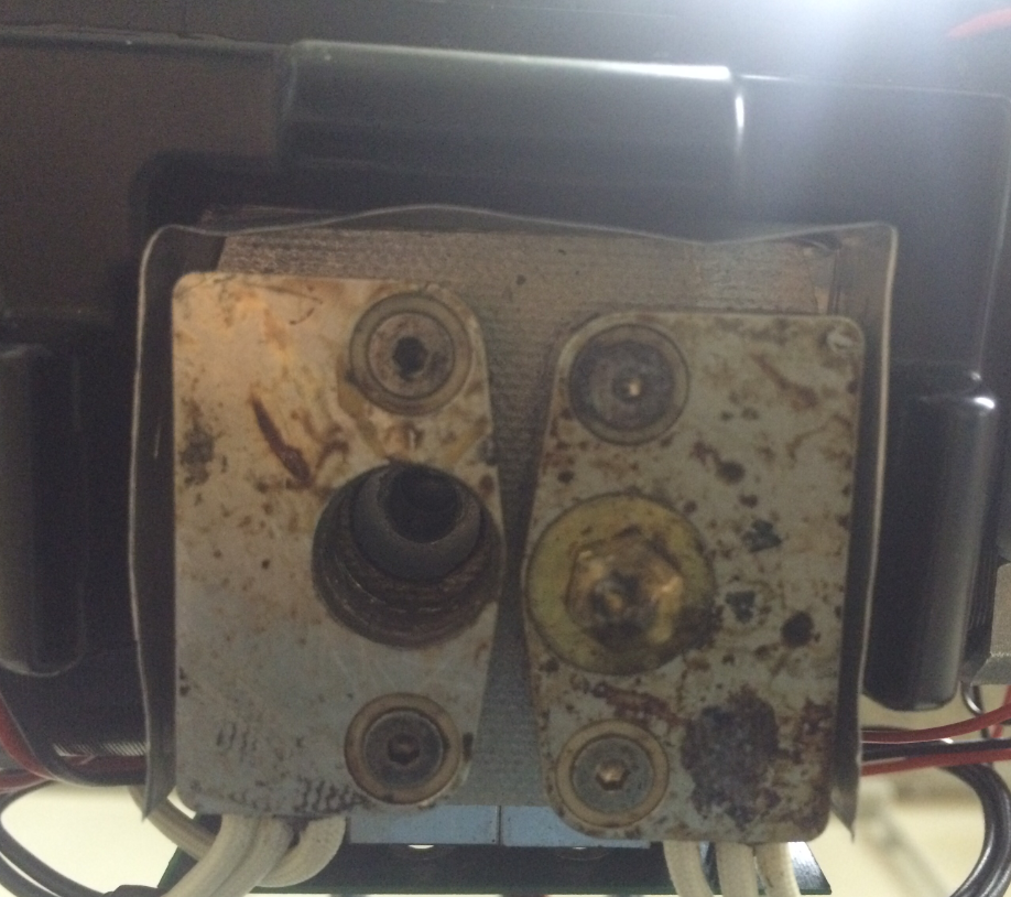
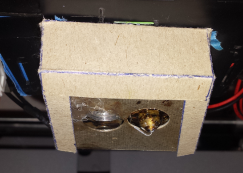
As you can see in the photo it encases it completely with the asbest? plate on the bottom from the original head cover.
It is not touching anything metal, but still the cooling airflow somehow affects the heater so that more than 60% is not possible. Furthermore the “block” is in the way of the air being blown to the nozzle, so that it only cools down the area 2cm off the actual print. So its useless for my overhang-curling problems.
I only used bent metal with no additional head cover or epoxy. The silicone nozzle protection I cannot use without the original head cover. And the original head cover with the silicone nozzle protection I do not want to use, as it is too close to the print bed surface and “collects” everything that is curling up a fraction of a mm. And as everything curls with my prints, I need to have a lot of space between print surface and print head.
I investigated but could not see any error and thus gave up on this solution.
Using the original head cover with some aluminium foil “heatshield”, without the silicone nozzle protection, does a better job than my bent metal sheet solution.
Ahh… Here´s the point!
If you don´t use the cover, the air from the cooling fan won´t cool your heaterblock anymore because your shield covers it, but the brass piece of your extruder nozzle is still right in the airstream. That´s even worse than using no cooler at all, because then, the nozzletip is cooler than the rest of the heaterblock; And that is exactly what you NOT want to have. Your software shows 195°C (heaterblock), but your extruder has only ~180°C at the tip…
The original head cover is not only for design, It is also a “guide” for the air coming out of the three outlets: The air goes along the surface of the cover and the silicone piece protects the brass nozzles from being cooled down. So, the airstream only cools the plastic that has already left the extruder.
If you really don´t want to use the cover, you will have to bring the air outlets much closer to the extruder and form the airstream in a way that it won´t affect the extruder nozzles too much. It´s a bit complicated, but possible.