Replacement parts

I have noticed that my ribbon cable, the broad on on the head, has some internal damage.
If bent a certain way or the head being in a specific area of the printbed, the head extruder motor stops working and does a clicking sound. The left extruder motor does the same clicking sound always, regardless of cable position.
There is no visible outside damage, so I would guess its some internal thing.
It is directly near the bridge, that holds the cable on the head, the damage occured. So there seems to be some sort of optimization needed.

Is this broad ribbon cable also some super Zim-special part or can this be bought somewhere?
Can you point me to a shop?

Thanks

This is nothing special. In fact, it could be replaced with some loose cables, bound together with some adhesive tape. Or you could look for some ribbon cable in any electronics store… Or, if available, take an old ATA Cable (The old grey ribbons, that were used in PCs for Harddisks or CD-ROM drives).
The tricky thing is the connectors. especially the one at the printhead is pretty hard to find. So maybe you would have to solder a bit for a new cable

Be carefull there is some power passing thru this cable. 2 Heater blocks (40W each) the steppers and the fans (2X 350mA).

the cable is a UL1007 Type 24AWG 18p 970mm length
One side is HRS2.54 2x9Pin connector and the other side is JST PHD2.0 2x9pin connector

Connection is straight 1 connected to 1… 18 to 18

It is important to keep the same path inside the frame if you want to keep operation with the top cover on the machine.

1 Like

Thanks you for the info.
I removed the cable and noticed its a crimped connector. Maybe I can somehow reuse it. I will try to carefully remove it.
So I don’t need to solder. Thats good for me, because I suck in soldering small or sensitive things.
I had to remove my top cover from day 1, because it either fell off or blocked the tubes and cable too much, so that prints failed or had damages inside.
I will order the parts and try to make some photos of my steps.

1 Like

It took a while but finally I was able to repair the cable.
I was not able to find another matching connector plug or cable.

After disassembling the plug and cable I noticed two broken wires, missing isolation on the sides (from the screws) and I know that some internal cable damage was also present. Its a miracle that the printer was not damaged by short circuits.

I simply removed the plug from the head, with a small screwdriver carefully removed the cables from the plug, cut the ribbon cable 5cm shorter, soldered the small metal plugs to the wires and stuck them back into the plug and to the head.
The original fixation with the plastic bridge and two screw wears down the isolation. To not damage the cable, plug or board, now I only use some isolation tape around the parts and where the PTFE tubes are running through. Its not perfect but seems better than the screw and plastic bridge solution.

Almost forgot to mention that both extruders now work again. I have to do some thorough testing on the weekend, but expect everything to work properly now.

2 Likes

Zeepro had a rash of bad crimps on these cables. I had one of them and they replaced it which solved a bunch of little issues I was having with jamming. I’ve been thinking this cable is going to wear out again since the crimps are not very good. It would be worth it to make this cable out of a more flexible ribbon cable. The wire does need to be a significant gauge though for the current to the motors and heaters as @Nightmare said. It’ll probably take another failure before I invest the time to build a new cable though :smile:

Instead of replacing you could remove the connectors and directly solder the cable on the PCB. THIS would be the solution :joy:
It’s simple, cheap and efficient. What else ? :sunglasses:

I think I rather rip my thumbnail off than to try to solder all of those wires directly into the PCB without melting the low temp PVC jacket… ok well maybe that’s too dramatic :slight_smile: But I’d still like to be able to easily disconnect it to repair the head assembly when necessary. Replacing the cable with individual silicone jacketed wires would be good, or if somehow you could find a silicone jacketed ribbon cable.

this PCB is just the transition between the Big ribon cable and all the small cables of the head. This means that can still unmount the head assebly by disconnecting the small cables.
Anyhow I gave the P/N of the connectors.

Without the top cover the cable and plug are not getting stressed much. So I do not expect any issues here anymore.

With the top cover the Zeepro solution is simply stupid and needs some improvements

  • first of all a more flexible cable
  • next a different plug socket that is not 90° angle, but straight
  • a better board fixation, because the board is very thin and fragile and only attached via the plastic bridge and two screws that damage the cable
  • a cable guide and protection, so that it runs clean and cannot bend downwards or get stuck

In normal operation the system is really working well. But the stupid thing is we start printing without the top cover. The top cover is really important fo the cable system.
As soon as you remove the top cover and start printing the cable writhe and the system becomes a pure shit.

My machine works fine and my cales are perfect. I always print with the top cover. the cables are tightened and centered so the screws dont damage the cables.

It is the only machine that is thin on top with hidden cables.

the only mod that we could imagine is to put a flexible teflon foil on the cable to have a better guidance.

1 Like

I completely disagree about this. For me, if I print with my top cover and deflector shield on, there is too much drag on the system and the X/Y gantry cannot move freely enough to be repeatable. So you end up getting shifted layers.

Here’s how I’m running things currently… with large spool holder on the back, and second extruder nozzle and tube removed (because sometimes this nozzle breaks prints free and it’s easy enough to change the filament).

I agree with BDub. My two Zim’s work much better with the top cover off, the head cover off, and the filament feed coming from the back. The only thing that concerns me at this point is that flimsy ribbon cable with it’s poor strain relief. It is under less strain with the top cover off because it isn’t rubbing up against it, and repeatedly bending down into the channel in the back. This part of the original design was a really poor choice. With repeated bending, that cable is going to fail. It’s not a matter of if, but when.

BDub maybe you had issues with the Teflon tubes. in my case evrything moves freely with the top cover on.
In your case is the teflon tube path is not correct i would have done like you :wink: 
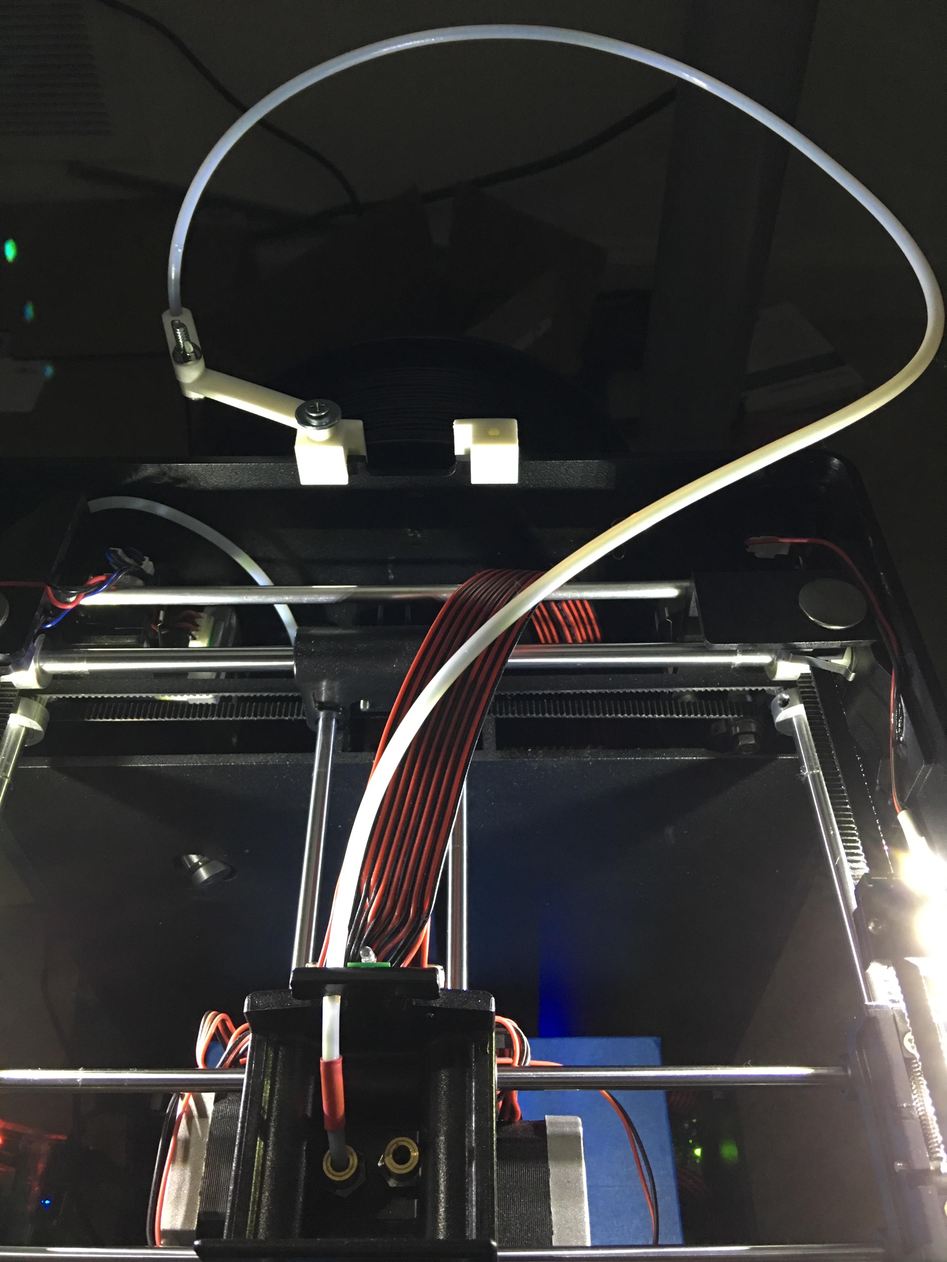
the tubes must do a loop on the base cover to absorb the head movement else the system can’t work correctly.
You have lot of chance not expriencing the same problem as jpod.

For my side i Used 2 Zims. mine and a friends one WITH the top cover and printing really often without any issues from this system
:smile:

I definitely had everything looped the way it was meant to be and it still bound up. Not complete jamming up… just adding resistance enough to miss steps when the gantry is trying to move around. You can see the difference in resistance if you move your gantry around manually with the covers on and off. Not having the tubes snake down and around the machine also help a bunch as in my picture above, but obviously harder to check the difference quickly. If your filament is unloaded, just pop the tubes out of the extruder to see. I’ve also recently taped my ribbon cable up on the back wall, so it doesn’t push and pull over the edge of the case. It may work for some people and some prints with a stock setup, but it doesn’t take a mechanical engineer to realize less restriction is better. And seeing failed prints vs beautiful prints is believing :wink: I also unplugged my bottom extruder steppers which were always powered before… less power running to them means more power is available for the rest of the system (if it needs it, this is hard to quantify without doing a bunch of measurements).

What really sealed the deal for me though, was my cartridges kept jamming inside them and filament would break just naturally coming out of the spool. Now I just feed the cartridges in from the top of my desk. I also modify the cartridges and remove the o-ring inside. Luckily I will run out of cartridges soon enough, and just use 1KG spools from then on.

Ok. for my side never missed any steps and the movements are really soft. As you can see I get really nice prints.
i have attached an image to illustrate the quality of the prints.

In you case mabe you have a bushing not centered or the gantry s not correctly aligned.

removinf the lower stepper is a good idea but more power on the head stepper ? your motors are not overheating ? Personnaly I woud reduce the power on the stepper driver. :wink: to avoid the head stepper to overhead and jam/melt the filament :smile:

By the way.

I have done a post on “Making our own replacement parts” but maybe I should have done it on this post ::blush:

"
Ok Guys

I need nozzles and it is impossible to get. So I will have to make my owns !

I found a factory that can manufacture me parts exactly same as the Genuine nozzles.

I am discussing the price with the manufacturer get the nozzles fully assembled

Now the price will be directly impacted but the quantities ordered.

For 100 nozzles we could have a unit price at 15 € without shipment the parts would made and shipped from France.

Who would be interested ? Can we match minimum 100 units or not ? "

More power “available”. The power supply only has so much power to supply (12V @ 10A) or something like that. So if things like stepper motors are being powered continuously (as stepper motors are when then are in a stopped braking idle condition) they will take away from the total available power. When another motor is being pulsed and the gantry moved… if that motor encounters a mechanical load like cabling or nozzle scraping over some previously cooled blobs, the current draw will go up substantially. If the current is not available to drive the motor through this “stall” condition (extra load), it will not move.

All that is to say, unplugging the extra motors just makes it easier for the remaining motors to generate a higher torque when necessary.

Your print looks great! Keep doing what you’re doing :slight_smile:

The bottom extruder motor and the head extruder motor are connected on the same stepper driver ! This stepper driver is calibrated to deliver much more current than the gantry and Z-axis stepper driver. There is a post concerning the power delivered by the extruder stepper drivers and how to calibrate them.
This means that if you disconnect the bottom extruder motor. the Head motor gets a little bit too much current from the driver witch will make it heat. in the case of the Extruder motor. during the print it is always powered or for extrusion or for braking. During a print you should try to feel the temp of the head motor. if you are extruding from the right nozzle look at the left motor temperature :wink:

In my case I print often Nylon Filament at temperatures of 270 and more. So I need to take care of the overall temp. specially from the extruder motor. If it start heating I may have filament Jam in the extruder section. I already experienced such problems.

Anyhow thank you for the electronic course :smiley:

Now I try to figure out if we can manufacture some nozzles :wink:

1 Like

I agree with @Nightmare ´s explanations. The steppers have a maximum current and the stepper driver electronics is adjusted to that current. You will easily burn out your Stepper Motors with 10A. This is why the current is limited in the stepper electronics.
If you look closely at the stepper drivers (underneath the Zimboard), you´ll notice that the micro-potentionmeter on the two Drivers for extruder 0 and 1 have a different position than the ones on the axis-stppers. Due normally two motors are attached to that driver, the max current preset is much higher (maybe twice the current :wink: ?).
I for myself adjusted the extruder-steppers down to the same value like the axis steppers. Not meterd, just visually turned it to the same position. Works good for me.